06-15-2012, 05:03 PM
(This post was last modified: 06-16-2012, 11:02 AM by henryarnold.)
My Grizzly G0519 Square Column Milling Machine is 5 years old this week. Some of you may know that I just finished a major repair of rebuilding the gear head. I've been enjoying using my "new" mill and was thinking of some of the upgrades that I have done to my mill over the years.
Once uncrated I had to build a stand and fit a VFD. The Grizzly G0519 came with a 3 phase motor so installing a VFD was required. Once I got these two projects finished and started using the milling machine, I quickly found that there is a lot of cranking needed when operating a mill. The least fun was cranking the 200 lbs of gear head up and down. I decided to motorize the Z axis as soon as possible.
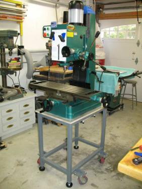
Here's the mill in its mostly stock state with the crank sticking out of the right hand side. Some of you may have a very similar mill with a crank on the left side. I wanted to motorize the Z axis and I was not concerned with maintaining the manual crank capability. If you want to be able to run under motor power and also be able to hand crank it, this modification is not for you because the crank is eliminated.
I tested the amount of power that would be needed to crank my Z axis using a drill motor. My first discovery was that I could easily lower the head but the the drill motor strained while lifting the head. I did a Google search and found many different ways that mill owners had used to counter balance their heads. I chose to use gas springs which are the piston looking objects used on almost every automobile with a lift gate. Gas Springs are powerful, compact, and inexpensive. I bought my gas springs surplus but they can be purchased from McMaster-Carr. The required stainless steel mounts can also be purchased at Mc Master-Carr.
My next task was to locate and inexpensive gear motor. A gear motor is required to lower the RPMs to a reasonable number. I had estimated that 2-3 turns per second is about the maximum speed that I could hand crank my Z Axis by hand and would be reasonable speed for a motorized solution. This comes out to about 150-200 RPMs.
I found this 180V right angle gear motor on EBay for $24. Right Angle DC gear motors are common and can be purchased inexpensively. The right angle feature makes it easier to tuck the motor to the side of the mill instead of having it stick out.
 n_a.jpg (Size: 10.19 KB / Downloads: 263)
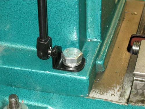
Next I needed to fabricate a method to mount the gas springs. I made a U shaped plate to fit around the head yoke with the gas spring ball mounts on either side. These mounts need to be as high up as possible so that the gas springs can expand to their full travel. This mount required two drilled and tapped holes in the yoke. The bottom mounts were cut from 1.5x1.5x3/16" angle iron. I bored a small hole for the ball mount and a large hole for the column mounting bolts which I used to retain the bottom mounts on each side.
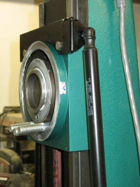
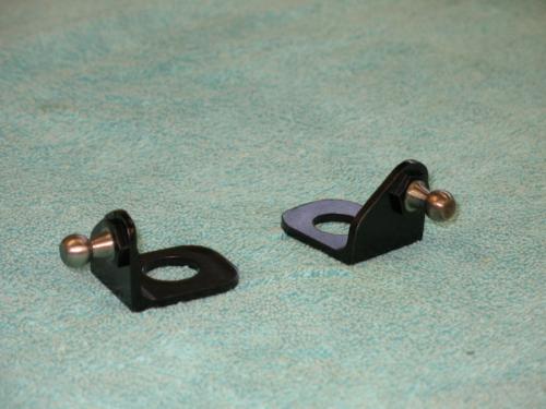
To save space, I TIG welded the stainless gas spring ball mounts from the back to their brackets. If you bolt them, it makes it impossible to use the method of using the column bolts to retain the bracket. There would be interference.
Here's a bottom mount with the gas spring installed.
Close up of the top bracket. The ball mount is welded to this bracket. All these brackets must be strong because of the 100 lbs of pressure exerted by each gas spring.
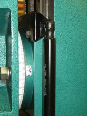
When you install the gas springs, the head must be at the top of its travel on the column so that the gas springs can be installed uncompressed. As you lower the head the gas spring compresses.
Warning: Never remove your gas spring without raising the head to the top of its travel where it will not be compressed.
Once uncrated I had to build a stand and fit a VFD. The Grizzly G0519 came with a 3 phase motor so installing a VFD was required. Once I got these two projects finished and started using the milling machine, I quickly found that there is a lot of cranking needed when operating a mill. The least fun was cranking the 200 lbs of gear head up and down. I decided to motorize the Z axis as soon as possible.
Here's the mill in its mostly stock state with the crank sticking out of the right hand side. Some of you may have a very similar mill with a crank on the left side. I wanted to motorize the Z axis and I was not concerned with maintaining the manual crank capability. If you want to be able to run under motor power and also be able to hand crank it, this modification is not for you because the crank is eliminated.
I tested the amount of power that would be needed to crank my Z axis using a drill motor. My first discovery was that I could easily lower the head but the the drill motor strained while lifting the head. I did a Google search and found many different ways that mill owners had used to counter balance their heads. I chose to use gas springs which are the piston looking objects used on almost every automobile with a lift gate. Gas Springs are powerful, compact, and inexpensive. I bought my gas springs surplus but they can be purchased from McMaster-Carr. The required stainless steel mounts can also be purchased at Mc Master-Carr.
My next task was to locate and inexpensive gear motor. A gear motor is required to lower the RPMs to a reasonable number. I had estimated that 2-3 turns per second is about the maximum speed that I could hand crank my Z Axis by hand and would be reasonable speed for a motorized solution. This comes out to about 150-200 RPMs.
I found this 180V right angle gear motor on EBay for $24. Right Angle DC gear motors are common and can be purchased inexpensively. The right angle feature makes it easier to tuck the motor to the side of the mill instead of having it stick out.
 n_a.jpg (Size: 10.19 KB / Downloads: 263)
Next I needed to fabricate a method to mount the gas springs. I made a U shaped plate to fit around the head yoke with the gas spring ball mounts on either side. These mounts need to be as high up as possible so that the gas springs can expand to their full travel. This mount required two drilled and tapped holes in the yoke. The bottom mounts were cut from 1.5x1.5x3/16" angle iron. I bored a small hole for the ball mount and a large hole for the column mounting bolts which I used to retain the bottom mounts on each side.
To save space, I TIG welded the stainless gas spring ball mounts from the back to their brackets. If you bolt them, it makes it impossible to use the method of using the column bolts to retain the bracket. There would be interference.
Here's a bottom mount with the gas spring installed.
Close up of the top bracket. The ball mount is welded to this bracket. All these brackets must be strong because of the 100 lbs of pressure exerted by each gas spring.
When you install the gas springs, the head must be at the top of its travel on the column so that the gas springs can be installed uncompressed. As you lower the head the gas spring compresses.
Warning: Never remove your gas spring without raising the head to the top of its travel where it will not be compressed.
henryarnold, proud to be a member of MetalworkingFun Forum since Apr 2012.


 ). Its not likely that I would run it too high because the travel is limited by the column height. On commercial installations, limit switches stop the motor when you have gone too far in either direction. You may want to consider adding them to your installation.