Posts: 8,889
Threads: 320
Joined: Feb 2012
Location: Arizona/Minnesota
I tried measuring the travel per revolution of the hand wheel again but used my Teclock dial indicator this time and the error wasn't as bad. Then I realized that if I didn't have the dial indicator at an exact 90 degree angle to the measuring surface, I would not get an accurate reading. So I lined up the Teclock as best as I could and it's much better. I went back and forth from my Teclock and my cheap dial indicator and my Noga and my cheap indicator holder and really couldn't nail down where all of the error is coming from. I didn't realize how hard it was to get a dial indicator at right angles to a surface in both directions. Anyway, I'm done measuring and am very happy with the results.
How does one measure the accuracy of a dial indicator anyway?

Ed
Posts: 2,344
Threads: 53
Joined: Feb 2012
Location: Spencer MA USA
Actually, you don't use an indicator for taking measurements of accuracy, just reference. If you were to truly gauge the lead, I would use a dial test indicator together with a gauge block setup. Place a plate across the ways, fasten a gauge block of a given length to it with a second one wrung to it leaving a shoulder. Attach a good dial test indictor on your Noga mag base, zero out the DTI at the end of the gauge block, lets say a 2" one, and zero the cross slide dial there too. Move it off and back on a couple of times to assure it repeats to the same spot on both at the start.
Now move the indicator off the block with a slight carriage movement in Z. Wind the cross slide in by almost 2", aiming the tip of the DTI at the second block's "landing spot". Looking at the DTI, bring it right to the same zero it was on at the first block. Now look at the dial on the cross slide. It should be on a "zero" if your cross slide dial is even turns to get from the start to 2" in. If it's not there, you have a pitch error.
It's easier to do than to describe, and If I had time I'd go do mine an post photos.
Posts: 8,889
Threads: 320
Joined: Feb 2012
Location: Arizona/Minnesota
Thanks Ken. I'll digest your post and give it a try tomorrow.
Ed
Posts: 716
Threads: 32
Joined: Apr 2012
Location: Washington, USA
If you want to test the tester, how about zeroing it against something and sliding a .010 feeler gauge under it?
Posts: 2,344
Threads: 53
Joined: Feb 2012
Location: Spencer MA USA
Been a while, got any update Ed?
Posts: 8,889
Threads: 320
Joined: Feb 2012
Location: Arizona/Minnesota
(07-10-2014, 08:30 PM)PixMan Wrote: Been a while, got any update Ed?
Not really. I've been working on getting the scale mounted back onto the cross slide. I'm making new brackets so I can regain the use of the cross slide lock. Once I get that done, I'll run some tests on the cross slide to see if the original problem has been fixed. I've got one more piece to make for the front bracket and then I need to make the rear bracket.
Ed
Posts: 8,889
Threads: 320
Joined: Feb 2012
Location: Arizona/Minnesota
The following 2 users Like EdK's post:
PixMan (07-19-2014), Mayhem (07-19-2014)
OK, finally an update to the project.
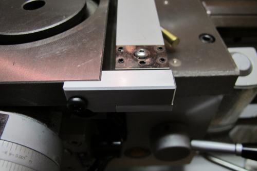
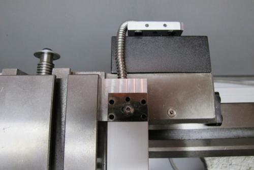
I wanted to get the DRO scale mounted so I could regain use of the cross slide lock. That required me to make new scale mounting brackets. That's done now and all back together. If you remember my complaint from post number 1, I was complaining about movement in the cross slide of between .015 - .020" as displayed by the DRO. I'm happy to report that the changes I've made have reduced the movement to less than .001".


I owe a lot of thanks to Ken for making me the new lead screw and nut for the cross slide. I doubt I would have been able to accomplish that on my own.
Tomorrow I'm going to do some real world testing to make sure it all works under power. I'll report back with the results.
Ed


